Push/Pull pots have been incredibly popular for guitarists for many years as they can help with alternative switching and tonal options without any real changes to the aesthetics of your guitar or the need to drill additional holes. They're regular pots but with an on/on DPDT switch mounted to the back casing allowing for some interesting wiring styles to be achieved.
If your control cavity allows (in regards to space available) then the CTS PCB Push/Pull pot is a superb, high quality option for your alternative switching needs. But does appear a little different to other equivalent push/pull pots on the market so I though it would be good to do a little spotlight on it and hopefully help explain those differences.

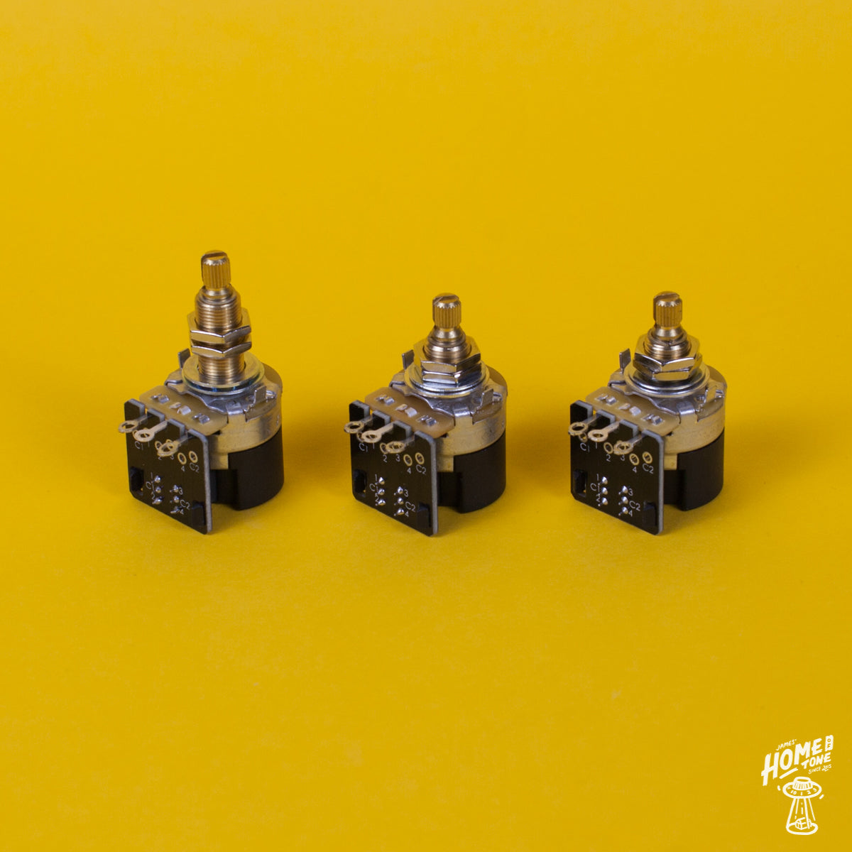
The traditional DPDT push/pull pot
Perhaps the most common push/pull pots on the market are the ones shown in the photo above. These are made with mini sized pots, which do have their advantages in terms of the minimal space/footprint taken up within the control cavity for example but can often lack the overall quality of a full sized CTS pot. Whether that's simply due tolerances, rotation feel or construction/longevity. This style of pot essentially features a regular DPDT switch mounted to the back casing of the pot and is operated via a push/pull or push/push pot shaft. The switch lugs, although small, are easily accessible and simple to wire up.

About the CTS Push/Pull pot
CTS produce a very high quality version of the push/pull pot which looks quite a lot different to these conventional versions mentioned above. You'll notice the overall size difference perhaps initially. That's because these are a full sized CTS pot instead of a mini sized pot and these ones in particular feature very similar specs to the high quality CTS standard pots I stock like the 'TVT' or '450' series, with brass pot shafts & +/-10% tolerance value. Which is one of the main reasons I really like these!
But instead of a traditional looking DPDT switch on the back like it's mini-pot counterpart, this has a large black casing with a PCB board mounted alongside the pot lugs. Here you have little numbered eyelets for your switch connections but they work very much in the same way once you have familiarised yourself with them. One little handy thing to note though are the slightly more traditionally laid out PCB lugs that look much more like the convension push/pull switch lugs. These are the ones on the PCB shown furthest away from the pot shaft on the photo below. These can be helpful if you're working with a wiring diagram that shows a traditional push/pull pot but you want to use this higher quality CTS push/pull instead for example, but also as the eyelets are numbered, things are pretty easy to follow here though once you get over the initial visual differences.

What do the numbered eyelets refer to?
Much like the standard DPDT Push/Pull, you have two 'common' eyelets, marked as C1 & C2. Those would be the same as the central two lugs on the regular DPDT push/pull. Alongside those are numbered eyelets 1 & 3, which correspond to the switch in it's pulled up location (the lugs that would be closest to the pot on a regular push/pull), and numbered eyelets 2 & 4 (the lugs that would be furthers away from the pot on a regular push/pull) which correspond to the switch in it's pushed down location. If you've ever wired up a regular push/pull pot then reading that will already likely start to feel more familiar.
Switch purposes
You could use a push/pull pot for so many purposes, phase switching, multiple tone capacitor options, coil tapping etc. But one of the most popular uses for a push/pull is to achieve coil splitting for humbucker pickups so let's start off by looking at how you would wire the switch for this function. When you're 'splitting' a humbucker, you're basically putting the signal from one of the humbucker coils to ground, resulting in a 'single coil' so to speak.
Up until learning a little more about guitar wiring over the years, I'll be honest, I really didn't like the coil split sound. I couldn't help but feel that a humbucker rarely ever sounds as good split as a true single coil would. Often sounding thin, brittle or too bright for example. This, as with anything guitar tone related, is of course subjective, the examples I tried may simply have been pickup models that don't lend themselves well to coil split, or component choices that don't do it justice. So I'm not totally closed minded on the subject, just skeptical of it's benefits shall we say lol. Some may like it as is and find the position very useful so the best way to find out is to try it for yourself rather than take people's word for it on the internet! (Even I admit that, given the irony of writing a post about it!! Personal preference is best when it comes to guitar sounds).

Wiring it up
Here we go then! For ease of translation I have simply decided to refer to Seymour Duncan's 4 conductor colour coding. They're perhaps the most widely used wiring colour codes and the easiest to find conversion diagrams so figured it would be simplest to use their colour coding for this diagram.
You could use either the C1 or C2 eyelets here, for the sake of this example I have shown it on the C1 side. It may simply come down to convenience within the control cavity to which side you use, you might have easier access on one side of the pot to the other within the cavity, so I'll keep the diagram simple and show it via C1 but will explain which number eyelets you would use if using C2. If you're coil splitting two humbuckers via one push/pull, then you may choose to make things a little less claustrophobic and use both sides of the switch instead of trying to fit multiple wires into one eyelet. Plenty of options!
Finally getting stuck in
First of all, I would prepare my ground, just use a length of plain wire for example. This would be located in the number 1 (if using C1 side) or number 3 (if using C2 side) eyelet with the other end of the wire soldered to the pot's metal casing. There isn't much real estate of metal pot casing on these, as the plastic switch casing covers the majority of the pot, but just use the side of the pot casing here.
Why the number 1 or 3 eyelets? Well when the push/pull pot is pulled upwards, those eyelets would be selected via the PCB causing the signal from the common eyelets to find it's way to ground and be removed from the live signal.
Which leads me now to the common connections, and the C1 eyelet in this example. Here you want to attach your pickups' 'series link' wires which are the north coil finish wire and the south coil finish wire. For Seymour Duncan, they are the red and white wires, which are put together and soldered to the C1 eyelet (or the C2 if using that side).
Now simply solder the usual pickup's ground wires to ground, this could be on the metal pot casing, or another point of ground on your wiring harness. Again, for Seymour Duncan these are the Green and bare/silver wires. Then finally, you will have your main pickup 'hot' wire, which will need to be connected to the relevant connection on your harness depending on which position you intend on installing the push/pull pot, IE Volume or Tone. Usually one of the pot lugs or your pickup selector. There are so many guitar models and wiring styles so couldn't really go into full detail on this without showing loads of diagrams, so have just concentrated on how to wire the actual DPDT switch in this article.

& you're ready! That's the DPDT PCB switch connections made, and ready to achieve coil split tones.
There are so many ways you could wire up a push/pull pot, but seeing as coil splitting is the most popular use I thought it would be good to highlight this first and maybe future articles look at alternative options. But I hope you enjoyed this read and found it helpful! Thanks for reading.
Want to order a CTS Push/Pull pot? I stock them here at James' Home of Tone and they can be found HERE
James
Have you made good use of some of the free resources here? Wired up your guitar or found useful info here along the way? Perhaps you might consider kindly supporting this free resource for guitarists via 'Buy me a coffee'! Thank you so much!
If your control cavity allows (in regards to space available) then the CTS PCB Push/Pull pot is a superb, high quality option for your alternative switching needs. But does appear a little different to other equivalent push/pull pots on the market so I though it would be good to do a little spotlight on it and hopefully help explain those differences.
The traditional DPDT push/pull pot
Perhaps the most common push/pull pots on the market are the ones shown in the photo above. These are made with mini sized pots, which do have their advantages in terms of the minimal space/footprint taken up within the control cavity for example but can often lack the overall quality of a full sized CTS pot. Whether that's simply due tolerances, rotation feel or construction/longevity. This style of pot essentially features a regular DPDT switch mounted to the back casing of the pot and is operated via a push/pull or push/push pot shaft. The switch lugs, although small, are easily accessible and simple to wire up.
About the CTS Push/Pull pot
CTS produce a very high quality version of the push/pull pot which looks quite a lot different to these conventional versions mentioned above. You'll notice the overall size difference perhaps initially. That's because these are a full sized CTS pot instead of a mini sized pot and these ones in particular feature very similar specs to the high quality CTS standard pots I stock like the 'TVT' or '450' series, with brass pot shafts & +/-10% tolerance value. Which is one of the main reasons I really like these!
But instead of a traditional looking DPDT switch on the back like it's mini-pot counterpart, this has a large black casing with a PCB board mounted alongside the pot lugs. Here you have little numbered eyelets for your switch connections but they work very much in the same way once you have familiarised yourself with them. One little handy thing to note though are the slightly more traditionally laid out PCB lugs that look much more like the convension push/pull switch lugs. These are the ones on the PCB shown furthest away from the pot shaft on the photo below. These can be helpful if you're working with a wiring diagram that shows a traditional push/pull pot but you want to use this higher quality CTS push/pull instead for example, but also as the eyelets are numbered, things are pretty easy to follow here though once you get over the initial visual differences.
What do the numbered eyelets refer to?
Much like the standard DPDT Push/Pull, you have two 'common' eyelets, marked as C1 & C2. Those would be the same as the central two lugs on the regular DPDT push/pull. Alongside those are numbered eyelets 1 & 3, which correspond to the switch in it's pulled up location (the lugs that would be closest to the pot on a regular push/pull), and numbered eyelets 2 & 4 (the lugs that would be furthers away from the pot on a regular push/pull) which correspond to the switch in it's pushed down location. If you've ever wired up a regular push/pull pot then reading that will already likely start to feel more familiar.
Switch purposes
You could use a push/pull pot for so many purposes, phase switching, multiple tone capacitor options, coil tapping etc. But one of the most popular uses for a push/pull is to achieve coil splitting for humbucker pickups so let's start off by looking at how you would wire the switch for this function. When you're 'splitting' a humbucker, you're basically putting the signal from one of the humbucker coils to ground, resulting in a 'single coil' so to speak.
Up until learning a little more about guitar wiring over the years, I'll be honest, I really didn't like the coil split sound. I couldn't help but feel that a humbucker rarely ever sounds as good split as a true single coil would. Often sounding thin, brittle or too bright for example. This, as with anything guitar tone related, is of course subjective, the examples I tried may simply have been pickup models that don't lend themselves well to coil split, or component choices that don't do it justice. So I'm not totally closed minded on the subject, just skeptical of it's benefits shall we say lol. Some may like it as is and find the position very useful so the best way to find out is to try it for yourself rather than take people's word for it on the internet! (Even I admit that, given the irony of writing a post about it!! Personal preference is best when it comes to guitar sounds).
Wiring it up
Here we go then! For ease of translation I have simply decided to refer to Seymour Duncan's 4 conductor colour coding. They're perhaps the most widely used wiring colour codes and the easiest to find conversion diagrams so figured it would be simplest to use their colour coding for this diagram.
You could use either the C1 or C2 eyelets here, for the sake of this example I have shown it on the C1 side. It may simply come down to convenience within the control cavity to which side you use, you might have easier access on one side of the pot to the other within the cavity, so I'll keep the diagram simple and show it via C1 but will explain which number eyelets you would use if using C2. If you're coil splitting two humbuckers via one push/pull, then you may choose to make things a little less claustrophobic and use both sides of the switch instead of trying to fit multiple wires into one eyelet. Plenty of options!
Finally getting stuck in
First of all, I would prepare my ground, just use a length of plain wire for example. This would be located in the number 1 (if using C1 side) or number 3 (if using C2 side) eyelet with the other end of the wire soldered to the pot's metal casing. There isn't much real estate of metal pot casing on these, as the plastic switch casing covers the majority of the pot, but just use the side of the pot casing here.
Why the number 1 or 3 eyelets? Well when the push/pull pot is pulled upwards, those eyelets would be selected via the PCB causing the signal from the common eyelets to find it's way to ground and be removed from the live signal.
Which leads me now to the common connections, and the C1 eyelet in this example. Here you want to attach your pickups' 'series link' wires which are the north coil finish wire and the south coil finish wire. For Seymour Duncan, they are the red and white wires, which are put together and soldered to the C1 eyelet (or the C2 if using that side).
Now simply solder the usual pickup's ground wires to ground, this could be on the metal pot casing, or another point of ground on your wiring harness. Again, for Seymour Duncan these are the Green and bare/silver wires. Then finally, you will have your main pickup 'hot' wire, which will need to be connected to the relevant connection on your harness depending on which position you intend on installing the push/pull pot, IE Volume or Tone. Usually one of the pot lugs or your pickup selector. There are so many guitar models and wiring styles so couldn't really go into full detail on this without showing loads of diagrams, so have just concentrated on how to wire the actual DPDT switch in this article.
& you're ready! That's the DPDT PCB switch connections made, and ready to achieve coil split tones.
There are so many ways you could wire up a push/pull pot, but seeing as coil splitting is the most popular use I thought it would be good to highlight this first and maybe future articles look at alternative options. But I hope you enjoyed this read and found it helpful! Thanks for reading.
Want to order a CTS Push/Pull pot? I stock them here at James' Home of Tone and they can be found HERE
James
Have you made good use of some of the free resources here? Wired up your guitar or found useful info here along the way? Perhaps you might consider kindly supporting this free resource for guitarists via 'Buy me a coffee'! Thank you so much!

Comments
Hey Alex,
Ah nice! My answer to Scott is nestled somewhere below, or above your comment (depending on where it places it on your screen! But the answers in regards to wire the guitar that way, is here in the comments from my old reply to that question :)
Hey Scott is apparently doing the same wiring as I am lol
“Hi, I have a push pull pot to coil split my bridge and neck humbuckers. I do not have a tone pot and i use a 3 way sel. switch. Could you forward me some info on how I can wire the push pull pot to coil split both humbuckers? Thank you.”
Thanks a bunch
Hiya Scott,
Sorry for missing this comment until now buddy.
No worries at all, can certainly help with that. So for coil splitting two humbuckers via one push/pull pot, it is thankfully just as simple as coil splitting one humbucker. The CTS push/pull is a double position, double throw switch so think of it as two switches in one essentially. In the drawn diagram in this article where I show the connections for coil split of one humbucker, follow that for the one humbucker. So a ground wire from eyelet 1 to the pot casing, and solder your neck pickup series link wires together into eyelet C1.
Then for the bridge pickup, solder a ground wire between eyelet number 3, and then solder your bridge pickup series link wires together into eyelet C2.
You neck and bridge ‘hot’ wires both then go to your 3 way toggle switch to the relevant side connections. And solder your pickup ground wires to the most convenient point of ground, either the switch ground lug if easiest or the pot casing for example.
Hope this helps,
James
Hi, I have a push pull pot to coil split my bridge and neck humbuckers. I do not have a tone pot and i use a 3 way sel. switch. Could you forward me some info on how i can wire the push pull pot to coil split both humbuckers? Thank you.
Thank you so much for this! Extremely helpful <3